
The connectors and adapters are coded throughout to ensure the correct orientation of the plug connection. The three polarity methods A, B and C as defined in TIA-568-C, for their part, are used to guarantee the right bi-directional allocation. This chapter describes these methods briefly.
Method A
Method A uses straight-through type A backbones (pin1 to pin1) and type A (key-up to key-down) MPO adapters. On one end of the link is a straight-through patch cord (A-to-B), on the other end is a cross-over patch cord (A-to-A). A pair-wise flip is done on the patch side. Note that only one A-to-A patch cord may be used for each link. MPO components from R&M have been available for Method A since 2007. It can be implemented quite easily, because e.g. just one cassette type is needed, and it is probably the most widespread method.
Method B
Method B uses cross-over type B backbones (pin1 to pin12) and type B (key-up to key-up) MPO adapters. However, the type B adapters are used differently on the two ends (key-up to key-up versus key-down to key-down), which requires more planning effort and expense. A straight-through patch cord (A-to-B) is used on both ends of the link. Method B does not enjoy wide use because of the greater planning effort and expense involved and because singlemode MPO connectors cannot be used. R&M does not support this method either or does so only on request.
Method C
Method C uses pair-wise flipped type C backbones and type A (key-up to key-down) MPO adapters. A straight-through patch cord (A-to-B) is used on both ends of the link. In other words, the pair-wise flip of polarity occurs in the backbone, which increases the planning effort and expense for linked backbones. In even-numbered linked backbones, an A-to-A patch cord is needed. Method C is not very widespread either because of the greater planning effort and expense involved and because it does not offer a way of migrating to 40/100GbE. R&M does not support Method C or does so only on request.
Method R
Method R (a designation defined by R&M) has been available since 2011. It requires just one type of patch cord (A-to-B). The crossover of the fibers for duplex signal transmission (10 GBase-SR) takes place in the pre-assembled cassette. The connectivity diagram for the trunk cable and patch cord or the light guidance remains the same all the time, even for parallel transmission (Method B) for setting up 40/100 GbE installations. That means capacity can be expanded directly in an uncomplicated and inexpensive manner. In addition, the only thing that has to be done is replace the cassettes with panels.
A specific lengths pre-assembled MTP/MPO Trunk cable with 12 or 24 fibers is delivered to data center for easy installation, because an It is impossible to manually to assemble MPO/MTP plug connector with 12 or 24 fibers on site during installation.
The advantages of MPO/MTP Trunk cable with the following advantages
• Higher Quality
Higher quality is usually achieved through factory assembly and inspection of individual parts. A factory-prepared inspection certificate is also useful for longterm documentation and in turn quality assurance purposes.
• Minimum Skew
A crucial factor in achieving a successful parallel optical connection is keeping the signal offset (skew) between the four or ten parallel fibers to an absolute minimum. Only in this way can information be successfully re-synchronized and re-combined at its destination. Factory-assembled trunk cables allow skew to be measured, minimized and logged.
• Shorter Installation Times
Pre-assembled MPO cable systems provide plug-and-play advantages and can be inserted and set up immediately.
This reduces installation time enormously
• Better Protection
Because they are completely assembled at the factory, cables and plug connectors remain completely protected from
environmental influences. Optical fibers that lie open in splice trays are at a minimum exposed to ambient air and may age faster as a result.
• Smaller Cable Volumes
Smaller diameters can be realized in MPO cabling systems that are produced from loose tube cables. The results are
correspondingly smaller cable volumes, better conditions for acclimatization in the data center and a lower fire load.
• Lower Overall Costs
When splice solutions are used, a few factors that are not always foreseeable boost total costs: time-intensive,
equipment-intensive splicing, needs for specialty works, bulk cables, pigtails, splice trays, splicing protection, holders. In contrast, pre-assembled trunk cables not only bring technical advantages, but usually result in lower total costs than splicing solutions.
Inspection should be done first before cleaning as it can decide if you need to clean. Once cleaning is required, dry cleaning which is an efficient method to remove dusts and finger grease is usually the preferred method to use due to the possibilities of residue when using alcohol based products.
However, dry cleaning method is not always sufficient to completely remove all contaminants. Thus, if the second inspection reveals that the MPO/MTP connector is still contaminated after the first dry cleaning, wet+dry cleaning method (Figure 4) is recommended to use for second cleaning. If the connector is still contaminated after second cleaning using wet+dry method, you could try to redo it once more. But in this case, permanent damage of the connector must be excluded. Once permanent damage is detected, the connector has to be replaced.
 Figure 4. Wet+Dry Cleaning
Tips: Always reinspect connector after cleaning!
Cassette cleaner and one-click MPO/MTP cleaner are both available for MPO/MTP connector dry cleaning.
Cassette cleaner (Figure 5) is designed for effective cleaning of almost all fiber optic connectors with an accessible ferrule including LC, MU, SC, FC, ST, MPO/MTP, MTRJ and so on. If you only need to clean the accessible connector with a wide range of connector styles, it is an ideal choice for you. Moreover, by replacing the tape, it is more cost-effective for long-term use. But always remember that don’t reverse cleaning direction to avoid bringing back the wiped contaminants while using cassette cleaner.
 Figure 5. Use Cassette Cleaner to Clean MTP Connector
The one-click MPO/MTP cleaner (Figure 6) is an easy-to-use cleaning tool for MPO/MTP accessible connector and adapter cleaning. If connector and adapter are both required to clean in your system, it is a good choice for you. Just with a simple “one-click”, the cleaning is done. A one-click MPO/MTP cleaner can be used up to 600 cleans.
 Figure 6. Use One-click MPO/MTP Cleaner to Clean MTP Connector
In addition to the cleaner, other cleaning accessories such as lint-free wipe, optical grade dust remover, lint-free swab, etc. are necessary to achieve dry or wet+dry cleaning.
 |  |  |
Fiber optic cleaning is a key part in whole fiber optic systems. MPO/MTP connector is more susceptible to contamination due to its larger contact area and multiple fiber design. Thus, choosing a right cleaning method and cleaning tool is very important for MPO/MTP cleaning. This post recommended cleaning methods and tools for MPO/MTP cleaning. .
MPO/MTP connector is the most common multi-fiber connector type used in today’s high-density networks, e.g. 40/100 Gigabit Ethernet. It usually contains one or two rows of fibers (12-fiber MPO/MTP or 24-fiber MPO/MTP) in a single connector. Compared to the single-fiber connectors, a MPO or MTP connector has a larger contact area (Figure 1), and alignment of the fibers is achieved by the connection of male connector (pinned connector) which has outer pins and female connector (unpinned connector) which has alignment holes (Figure 2).

Figure 1. MPO/MTP Connector VS. Single-Fiber Connector (LC Connector)

Figure 2. Male & Female MPO/MTP Connectors
When cleaning a MPO/MTP connector, all fibers on the connector must be clean for it to function properly. Because contamination of one fiber can cause signal degradation on other fibers. Additionally, due to the presence of the alignment pins, the cleaning of the extreme sides of the MPO/MTP connector end-face is often overlooked by users (Figure 3). This is also why we cannot get the expected result in spite of repetitive cleaning. For these reasons, we should choose the right cleaning method and tools for proper cleaning.
 Figure 3. Cleaning Dead Zone of MPO/MTP Male Connector
 Figure 2: Type-B polarity MTP cable types
Figure 2: Type-B polarity MTP cable types


Uniformity(dB) = 10 log(P0/P1) - 10 log(P0/P2)] = 10 log(P2/P1)
 Figure 1: fiber optic connector structure

Figure-5: Cleaning Methods for Fiber Optic Adapter
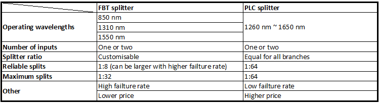
Also it is pretty clear visually shown on a infographic above (at least we hope so, as a lot of work are done to create above infograph), here’s a description of what you can see above.
Optical networks require signal being splitted somewhere in design to serve for multiple customers. Splitter technology has made a huge step forward in the past few years by introducing PLC (Planar Lightwave Circuit) splitter. It has proven itself as a higher reliable type of device compared to the traditional FBT (Fused Biconical Taper) splitter. While being similar in size and outer appearance, both types of splitters provide data and video access for business and private customers. However, internally the technologies behind these types vary, thus giving service providers a possibility to choose a more appropriate solution.
FBT splitter is made out of materials that are easily available, for example steel, fiber, hot dorm and others. All of these materials are low-price, which determines the low cost of the device itself. The technology of the device manufacturing is relatively simple, which has the impact on its price as well. In scenario where multiple splits are needed, the size of the device may become an issue. It is important to keep in mind that splitters are being deployed in the fields either in cabinets or in strand mountings, so the size of device plays a critical role. FBT splitters only support three wavelengths (850/1310/1550 nm) which makes these devices unable to operate on other wavelengths. Inability of adjusting wavelengths makes FBT splitters less customizable for different purposes. Moreover, the devices are to a high extent temperature sensitive, providing a stable working range of -5 to 75 C. In certain areas, such as Scandinavian countries this temperature restrictions may be crucial. The signal processed by FBT splitters cannot be splitted evenly due to lack of management of the signals
PLC splitter manufacturing technology is more complex. It uses semiconductor technology (lithography, etching, developer technology) production, hence it is more difficult to manufacture. Therefore, the price of the device is higher. However, there is a number of advantages the device possesses. The size of the device is compact, compared to FBT splitters, making it suitable for density applications. PLC splitter operates at wider temperature range (-40 to 85 C), allowing its deploying in the areas of extreme climate. The split ratio goes up to 64, providing a high reliability. Furthermore, the signal can be split equally due to technology implemented. A range of wavelengths (1260 – 1650 nm) is provided, so the wavelengths are adjustable. Critical points of the device that might fail are input and output, so the general risk of failure is low.

Detailed Picture(Offset)

If your gigabit LX switch is equipped with SC or LC connectors,please be sure to connect the yellow leg(Singlemode)of the cable to the transmit side,and the orange leg(multimode)to the receive side of the equipment.It is imperative that this configuration be maintained on both ends.The swap of transmit and receive can only be done at the cable plant side.(see diagram below)

Common fiber optic cable is fragile, which needs to be protected, especially when in harsh applications where cables could be compromised by rodents, constant wear and tear or weather damage. Armored fiber patch cable retains all the features of standard fiber cable but is much stronger due to its extra layers of armor. With the protection of flexible and durable steel tube, armored fiber patch cable will ensure the excellent operation of your network.

Ideal for harsh installation conditions that require exceptional durability. It is used as interconnection or cross connection in data center. It is also used in ceiling, corridor and other harsh environment.
Prepare the fiber testers you need
1.Use a cable stripper to strip the outside coating of the cable to expose the active wire underneath. Usually, stripping a wire or cable involves scoring the coating to the cable to detach it so it slides away from the outside of the wire without damaging the wire.
2. Generally test every 10 fiber optic connectors need to re-manufacturing optical fiber, each test need to check the fiber If it is damaged.
3. Cut drop the protective layer of the cable as far as possible, instead of with a wire stripper, to reduce the damage of the fiber cable. When use a wire stripper, bent the fiber optical cable 60 degrees in four directions, check the fiber if it is intact. At present, many wire strippers are poor quality, easy to damage the fiber optic, must particularly stressed.
4. The use of imported fiber cleaver, such as Sumitomo FC-6S, complete the pressure optical fiber surface and keep the cutting surface clean, to ensure excellent cutting quality. Excellent cutting surface is flat with the end face of the tilt angle is less than 0.5 degrees and no glitches. Poor Cutting surface the end tilt angle is large and there are glitches. Burr fiber optic inserted into the fiber fast connector may appear broken fiber, fiber butt gap and so on, will leading to a loss of circuit of the products.
The attentions you should mind during the testing process
1. The end surface cleaning first with dust-free paper which is moistened with alcohol, then dry the end surface with dry dust-free paper.
2. Use a combination of fiber light source and optical power meter for testing, prepare the fiber patch cord to the light source, mind the end surface insertion loss less than 0.1dB. The flange test need to use high-quality flanges, the traditional 1-2yuan flange with poor quality, test dozens or hundreds of times, the parameters may deteriorate. Using wire jumper to do the fiber optic cable test, making optical fiber fast connector connected to the fiber under test. Mind the covered wire jumper end surface insertion loss below 0.1dB.
3.Regular cleaning flange ceramic sleeves and special swabs which are covered when test fiber optical connectors, using air-laid paper and ceramic ferrule end face of the fiber jumpers. When suspect flange and fiber jumpers pointer exception, can through the comparative analysis of replace flange and fiber jumpers. General fiber jumpers and flange allows mating cycles of 500 times, need to replace the damaged fiber jumpers and flange timely.
4. When the test index is unnormal, should pay attention to the fiber microbending whether is under the specified range, check the fiber is a broken or existence of a fiber cut.
5. Surface contamination will affect the test parameters, need to prepare the surface detector, check the end cleaning quality when abnormal.
The Method when test data is abnormal
1. Indicators in the 0.3-0.5dB, clean the end surface and retest.
2. Indicators above0.5dB, clean the end surface, re-prepare a test fiber and re-test.
When to Replace Electrodes of Your Fusion Splicing Machine
What’s the best time to replace the electrodes of your fusion splicing machine, and how do you know when to replace it? Different users have different methods according to their working experiences. But the most basic method to judge when to replace the electrodes will be introduced here. Generally, there are two basic ways to judge whether the fusion splicing machine needs to be replaced its electrodes.
There is a function of a fusion splicing machine called arc discharge count. Electrodes should be replaced after reaching the manufactures recommended arc discharges. In general, the fusion splicing machine will alarm to remind users to replace the electrodes in that case. You should replace the electrodes of your fusion splicing machine when you see this alarm. Otherwise, splicing loss and quality will be effected.
Users can confirm whether the electrodes need to be replaced through some abnormal conditions during using. For example, if you find that your fusion splicing machine often prompt discharge not stable during the splicing, or discharge correction can not pass normally, or even the tip of the electrodes are oxidate severely and bald, you should replace the electrodes in those cases.
How to Replace Electrodes of Fusion Splicing Machine
Electrodes Replacing Steps
We can see the electrodes replacing steps in the following picture. It shows us the electrodes replacing steps of the Fujikura latest FSM-80S fusion splicing machine.

Tips for Replacing Electrodes
After replacing the electrodes, it’s necessary to stabilize the electrode and conduct discharge correction in order to make sure that the new electrodes perform well. These can usually be done through instructions of the fusion splicing machine. In addition, we should use the discharge correction feature to get the best discharge power of the machine in daily use.
5G is the “fifth generation” of wireless networks. It will cover a wide range of devices, including both mobile and fixed network infrastructure, i.e. both mobile smartphones, wearables and settled machines will be wireless. So does that mean in future we will need no fiber cables running around?
At first glance, people may think 5G wireless will work via radio signals and no fiber will be used. On the contrary, the success of future 5G significantly depends on fiber.
Beneath the surface of the world’s wireless infrastructure lies a big net interwoven by the fiber optic cables. And at present 90% of all internet traffic travels over wireline fiber, even if it finally terminates in a wireless device.

5G is targeted at a connection speed of 1-10 Gbps, which is ten to hundred times higher than 4G. The overwhelming traffic to data centers will demand a transport media that is capable of high bandwidth and long distance, and fiber is the best future-proof choice among all mediums. For some big companies who know the role of fiber have invested more on it in preparing for 5G deployment, such as Verizon.

In order to meet the 5G promised performance goals (see the chart below), there needs to be more fiber deployed worldwide. Because the final target is not only about higher speed, but the sub-millisecond latency, network diversity, availability and coverage that all require a solid foundation of fiber.
| 1. 1-10Gbps connections to end points in the field (i.e. not theoretical maximum) |
| 2. 1 millisecond end-to-end round trip delay (latency) |
| 3. 1000x bandwidth per unit area |
| 4. 10-100x number of connected devices |
| 5. (Perception of) 99.999% availability |
| 6. (Perception of) 100% coverage |
| 7. 90% reduction in network energy usage |
| 8. Up to 10 year battery life for low power, machine-type devices |
The goals of 5G network diversity, availability and coverage can be obtained by wider deployment of small cell sites/distributed antenna systems (DAS) interconnected by fiber. Small cell sites/DAS (100-200 m/less than 30 m) are closer to users in location (on light or utility poles) compared with macro cell site (3-6 km), and can support a variety of technologies and frequencies.

By deploying more small cell sites/DAS, there can be fewer terminal users covered by each site and thus enabling higher per-user capacities. If the small cell sites/DAS need to work well in future 5G, the backhaul must be fiber since copper or air cannot support the immense amount of traffic that will be generated by 5G centralized radio access network (C-RAN).

In addition to ability, also considering the cost-effectiveness and TCO (total cost of ownership), fiber to the cell sites or tower is deemed the superior option. And of course more connections from these sites to data centers mean more fiber will be installed.
5G wireless will not abandon fiber. Instead its deployment will greatly rely on the availability of fiber infrastructure. Also the fiber will largely boost the capacity and lower latency in future generations of wireless networks.
This device is based on laser diode visible light source, when the light injected into the fiber, if fiber fracture, connector failure, bending over, poor weld quality failure by launching the light of the fiber to fiber fault visualization positioning.Visual Fault Locator launched a continuous wave (CW) or pulsed mode. The typical frequency of 1Hz or 2Hz, but can also work in the kHz range. Usually the output power of 0dBm (1mW) or less, the working distance of 2 to 5km, and to support all the common connector.
Visual fault locators generally include the pen type, handheld type and portable visual fiber fault locator. In addition, designed with a FC, SC, ST adapter, VFL is used without any other type of additional adapters, it can locates fault up to 10km in fiber cable, with compact in size, light in weight, red laser output.
The visual fault locator is commonly used for fiber identification and fault location of single-mode or multi-mode fiber as well as for wavelength loss testing. It is also an ideal tool for the examination of all types of patch cords and ribbon or bunched pigtails. It is an excellent tool for the maintenance of fiber optic networks, optical systems including LAN, FDDI and ATM, telecommunications and CATV networks. It is intended for the identification,fault location of fiber optics on single mode or multimode fiber and wavelength loss testing. It can also locate the fault of OTDR dead zone and make fiber identification from one end to the other end.