janewang@keweifiber.com
+86-0512-82691269   Whatspp: +86 18625257159

Cable Management

  • Q MPO/MTP Trunk Cable Advantages

    A specific lengths pre-assembled MTP/MPO Trunk cable with 12 or 24 fibers is delivered to data center for easy installation, because an It is impossible to manually to assemble MPO/MTP plug connector with 12 or 24 fibers on site during installation.MPO-MPO-Patch-cord-10m

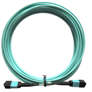
    The advantages of MPO/MTP Trunk cable with the following advantages

    Higher Quality
    Higher quality is usually achieved through factory assembly and inspection of individual parts. A factory-prepared inspection certificate is also useful for longterm documentation and in turn quality assurance purposes.

    Minimum Skew
    A crucial factor in achieving a successful parallel optical connection is keeping the signal offset (skew) between the four or ten parallel fibers to an absolute minimum. Only in this way can information be successfully re-synchronized and re-combined at its destination. Factory-assembled trunk cables allow skew to be measured, minimized and logged.

    Shorter Installation Times
    Pre-assembled MPO cable systems provide plug-and-play advantages and can be inserted and set up immediately.
    This reduces installation time enormously

    • Better Protection
    Because they are completely assembled at the factory, cables and plug connectors remain completely protected from
    environmental influences. Optical fibers that lie open in splice trays are at a minimum exposed to ambient air and may age faster as a result.

    Smaller Cable Volumes
    Smaller diameters can be realized in MPO cabling systems that are produced from loose tube cables. The results are
    correspondingly smaller cable volumes, better conditions for acclimatization in the data center and a lower fire load.

    Lower Overall Costs
    When splice solutions are used, a few factors that are not always foreseeable boost total costs: time-intensive,
    equipment-intensive splicing, needs for specialty works, bulk cables, pigtails, splice trays, splicing protection, holders. In contrast, pre-assembled trunk cables not only bring technical advantages, but usually result in lower total costs than splicing solutions.

  • Q Cleaning Method of MTP/MPO connector—Dry or Wet?

    Inspection should be done first before cleaning as it can decide if you need to clean. Once cleaning is required, dry cleaning which is an efficient method to remove dusts and finger grease is usually the preferred method to use due to the possibilities of residue when using alcohol based products.

    However, dry cleaning method is not always sufficient to completely remove all contaminants. Thus, if the second inspection reveals that the MPO/MTP connector is still contaminated after the first dry cleaning, wet+dry cleaning method (Figure 4) is recommended to use for second cleaning. If the connector is still contaminated after second cleaning using wet+dry method, you could try to redo it once more. But in this case, permanent damage of the connector must be excluded. Once permanent damage is detected, the connector has to be replaced.

    wet+dry cleaning methodFigure 4. Wet+Dry Cleaning

    Tips: Always reinspect connector after cleaning!

    Cleaning Tool—Cassette Cleaner or One-Click Cleaner?

    Cassette cleaner and one-click MPO/MTP cleaner are both available for MPO/MTP connector dry cleaning.

    Cassette cleaner (Figure 5) is designed for effective cleaning of almost all fiber optic connectors with an accessible ferrule including LC, MU, SC, FC, ST, MPO/MTP, MTRJ and so on. If you only need to clean the accessible connector with a wide range of connector styles, it is an ideal choice for you. Moreover, by replacing the tape, it is more cost-effective for long-term use. But always remember that don’t reverse cleaning direction to avoid bringing back the wiped contaminants while using cassette cleaner.

    cassette cleanerFigure 5. Use Cassette Cleaner to Clean MTP Connector

    The one-click MPO/MTP cleaner (Figure 6) is an easy-to-use cleaning tool for MPO/MTP accessible connector and adapter cleaning. If connector and adapter are both required to clean in your system, it is a good choice for you. Just with a simple “one-click”, the cleaning is done. A one-click MPO/MTP cleaner can be used up to 600 cleans.

    one-click cleanerFigure 6. Use One-click MPO/MTP Cleaner to Clean MTP Connector

    In addition to the cleaner, other cleaning accessories such as lint-free wipe, optical grade dust remover, lint-free swab, etc. are necessary to achieve dry or wet+dry cleaning.

    clean wipe swab dust remover


    Conclusion

    Fiber optic cleaning is a key part in whole fiber optic systems. MPO/MTP connector is more susceptible to contamination due to its larger contact area and multiple fiber design. Thus, choosing a right cleaning method and cleaning tool is very important for MPO/MTP cleaning. This post recommended cleaning methods and tools for MPO/MTP cleaning.  .

  • Q Understanding MPO/MTP Connector

    MPO/MTP connector is the most common multi-fiber connector type used in today’s high-density networks, e.g. 40/100 Gigabit Ethernet. It usually contains one or two rows of fibers (12-fiber MPO/MTP or 24-fiber MPO/MTP) in a single connector. Compared to the single-fiber connectors, a MPO or MTP connector has a larger contact area (Figure 1), and alignment of the fibers is achieved by the connection of male connector (pinned connector) which has outer pins and female connector (unpinned connector) which has alignment holes (Figure 2).

    MTP vs. LC
    Figure 1. MPO/MTP Connector VS. Single-Fiber Connector (LC Connector)

    male vs. female
    Figure 2. Male & Female MPO/MTP Connectors

    When cleaning a MPO/MTP connector, all fibers on the connector must be clean for it to function properly. Because contamination of one fiber can cause signal degradation on other fibers. Additionally, due to the presence of the alignment pins, the cleaning of the extreme sides of the MPO/MTP connector end-face is often overlooked by users (Figure 3). This is also why we cannot get the expected result in spite of repetitive cleaning. For these reasons, we should choose the right cleaning method and tools for proper cleaning.

    areas not cleaned by toolFigure 3. Cleaning Dead Zone of MPO/MTP Male Connector

  • Q Categories: Diverse Types to Meet Different Challenges

    In today’s fiber optic networks, especially in data centers, MTP trunk cable and MTP-LC harness cable are two most common types used. Besides, MTP connector is pin and socket connectors, which require a male side and a female side. Therefore, in terms of MTP trunk cable, there are female-female, female-male and male-male three types. In addition, when connecting two parallel optics 40G SR4 QSFP+ transceivers, only a female to female type-B MTP cable should be used. For MTP-LC harness cable, female MTP-LC harness cable and male MTP-LC harness cable are available.

    mtp type-b cable types Figure 2: Type-B polarity MTP cable types

  • Q Type-B Polarity MTP Cable User Guide

    As demand grows for higher speed, large data centers being built today have begun to make preparations for 40G/100G transmission. MTP cables, with great performance and high speed, have become the main component in data centers.

    In today's data centers, MTP cables, like 8-fiber or 12-fiber MTP cable, are frequently used to establish an optical path between switch tiers. Different from common fiber patch cords, one MTP cable has multiple fibers inside, which leads to more complex in the polarity management. Because the MTP connector terminates multiple fibers in a single high-density interface. And there are different fiber positions. To match these fiber position, TIA standards define three types of polarity MTP cables: type-A, type-B and type-C. Different types polarity cables may have different applications. In this tutorial, we will mainly introduce the type-B polarity MTP cables and its applications.

  • Q Why Choose Pre-terminated Cabling System For Data Center?

    To bring a data center online, getting high performance network with less time and money is always what people concern about. The termination and cabling of fiber optic links in today’s data center are necessary and usually take a lot of time and labor. In traditional ways, these fiber optic links are terminated on field. In some data centers, engineers still use the traditional methods to terminate fiber optic links for data center cabling. However, risks like signal loss are increased with the traditional field fiber optic termination. To increase the working efficiency and network performance with less time and money, pre-terminated fiber cabling solutions are being widely introduced in the modern data center.

    In fact, pre-terminated cables go through the same procedures as field terminated cables, but these steps are taken at the manufacturer’s facility or cable assembly house and delivered to the job site with the connectors already terminated, properly polished, and the entire cable assembly tested on either both end or one end. Which helps to eliminate the necessity for on-site field termination. Compared with field terminated cabling products, pre-terminated fiber cable assemblies are more convenient and flexible. They are most suited for network installations that are planned well in advance, taking into account both current and future requirements.

  • Q Port Configurations of Fiber Optic Couplers

    We can imagine a number of fiber conbinations that could be coupled by a device, some of which are shown in the figures below.

    2x1 Coupler1x2 Splitter

    Tree Coupler

    Star Coupler

    A 2 × 1 coupler is used to combine two light inputs into a single fiber (a). When the direction of light propagation is changed, this device will split one optical signal into two (b). In this operation, the coupler is called a fiber optic splitter in accordance with the function it performs. There are couplers that couple or split, 1 × N or N × 1 ports (c). They are called tree couplers and may have an N × M configuration. An important coupler for a WDM networks is a star coupler (d). In it the same number of ports serve as inputs and outputs. It is an N × N bidirectional (BIDI) coupler. However, a star coupler can be built as an N × M unidirectional coupler.

    A coupler with a 50:50 output ratio that is, a splitter is called a 3 dB coupler. This simple device can be used as the basic building block of tree and star couplers. However, this is not the best approach to take because we need M = (N/2) log2N 3-dB couplers to make an N × N star coupler and only 1/N portion of the power launched into each port will appear at every output. This is why modern tree and star couplers for broadcast WDM networks are fabricated directly using the FBT technique.

    Uniformity is the coupler characteristic used for equal split ratios. For example, an ideal 1 × 2 coupler would split the input power equally into two output ports. In reality, however, the power at each ouput port will vary from the 50:50 ratio. The physical reason for this inequality is different losses due to insertion for different couplings originated during the fabrication process. Uniformity for a 50:50 coupler is shown as below:

    Uniformity(dB) = 10 log(P0/P1) - 10 log(P0/P2)] = 10 log(P2/P1)

    It is a measure of the inequality of the split power in different fibers.

  • Q What Is Fiber Optic Connector?

    Fiber optic connector, or optical fiber connector, is a component to terminate the end of fiber optical cable, and enables quicker connection and disconnection than fiber splicing. It mechanically couples and aligns the fiber cores to make light pass successfully. Therefore, fiber optic connector has an important impact on the fiber optic transmission reliability and the performance of the system. Quality optical connectors lose very little light due to reflection or misalignment of the fibers.

    Fiber optic connector types are as various as the applications for which they were developed. Different connector types have different characteristics, different advantages and disadvantages, and different performance parameters. But all connectors have the same three basic components: ferrule, connector body, cable, coupling device.

    fiber optic connector structure Figure 1: fiber optic connector structure

    Ferrule: the ferrule acts as a fiber alignment mechanism and holds the glass fiber. It has a hollowed-out center that forms a tight grip on the fiber. Ferrules are typically made of metal, ceramic or quality plastic.

    Connector Body: also known as the connector housing, the body holds the ferrule and attaches to the jacket and strengthens members of the fiber cable itself. It is usually constructed of metal or plastic and includes one or more assembled pieces which hold the fiber in place.

    Coupling Device: coupling device is a part of the connector body that keeps the connector in place when attached to another device like as bulkhead coupler and optical transceiver.

  • Q Things to Know When Using Mode Conditioning Cables

    Mode conditioning patch cords are usually used in pairs.Which means that you will need a mode conditioning patch cord at each end to connect the equipment to the cable plant.Generally,Mode Conditioning patch cords are required for link distances greater than 984 feet(300 meters).

     3

    Detailed Picture(Offset)
    41

  • Q How to Install the Mode Conditioning Cable

    If your gigabit LX switch is equipped with SC or LC connectors,please be sure to connect the yellow leg(Singlemode)of the cable to the transmit side,and the orange leg(multimode)to the receive side of the equipment.It is imperative that this configuration be maintained on both ends.The swap of transmit and receive can only be done at the cable plant side.(see diagram below)

     2

     
  • Q Benefits of Armored Fiber Patch Cable

    Common fiber optic cable is fragile, which needs to be protected, especially when in harsh applications where cables could be compromised by rodents, constant wear and tear or weather damage. Armored fiber patch cable retains all the features of standard fiber cable but is much stronger due to its extra layers of armor. With the protection of flexible and durable steel tube, armored fiber patch cable will ensure the excellent operation of your network.

    A

    Ideal for harsh installation conditions that require exceptional durability. It is used as interconnection or cross connection in data center. It is also used in ceiling, corridor and other harsh environment.


  • Q Why is fiber preferred to copper or coaxial cable?

    Optical fiber is unique because it can carry a high bandwidth signal enormous distances.

    The longer the distance the signal travels on copper or coaxial cable, the lower the bandwidth.

    Fiber networks can also be upgraded by changing the electronics or using different lasers that increase the bandwidth

    without changing the fiber itself. That’s why fiber networks are said to be “future proof.”
  • Q Is it okay to print “Corning” on the cable your company provides?

    Yes. But we can only print “Coring Fiber Cable” not “Corning Cable” on our cables.
  • Q what is ONFCG cable

    OFCG stands for Optical Fiber Conductive General-Purpose. They have the same fire characteristics as OFNG cables but they have conducting armor or central strength members which is typically steel. OFCG cables should be properly grounded at both ends. They should not be installed in the same cable tray or conduits as power cables.
  • Q what is OFNG cable

     OFNG stands for Optical Fiber Nonconductive General-Purpose. They are typically used in horizontal cabling, single floor applications. OFNG cables can not be used in plenums or risers. OFNP and OFNR cables both can be used as substitutes for OFNG cables.
  • Q what is ONFCR cables

    OFCR stands for Optical Fiber Conductive Riser. OFCR cables have the same fire rating characteristics as OFNR cables but they have conducting armor or central strength member which is usually steel. OFCR cables should also be properly grounded at both ends. OFCP cables can be used as substitutes for OFCR cables. OFCR cables can not be installed in the same cable trays or conduits as power cables.
  • Q what is OFNR

    OFNR stands for Optical Fiber Nonconductive Riser. OFNR cables are used in Riser areas which are building vertical shafts or runs from one floor to another floor. OFNR cables can not be installed in plenum areas since they do not have the required fire and smoking rating as Plenum rated cables. OFNP plenum cables can be used as substitutes for OFNR cables.
  • Q What is OFNP for cable

    OFNP stands for Optical Fiber Nonconductive Plenum. OFNP cables have fire-resistance and low smoke production characteristics. They can be installed in ducts, plenums and other spaces used for building airflow. This is the highest fire rating fiber cable and no other cable types can be used as substitutes.
  • Q What is CPRI

    CPRI defines the publicly available specification for the key internal interface of radio base stations between the Radio Equipment Control (REC or base station) and the Radio Equipment (RE, or radio head). The companies cooperating to define the CPRI specification now include Ericsson, Huawei, NEC, Nokia Siemens Networks and Alcatel-Lucent. The CPRI specification has gone through several revisions, and today is at version 6.0.

    The idea behind CPRI was to create an open standard for interfacing base stations with radio heads, but in reality, CPRI is not common as it is not truly an open standard. Instead, similar to what happened with the Integrated Services Digital Network (ISDN) standard for PBXs, each base station manufacturer developed its own flavor of CPRI that works only when interfacing its own base stations with its own radio heads. Since most major base station manufacturers don’t make DAS equipment, DAS systems supplied by third party OEMs until now haven’t been able to interface the DAS head end equipment directly with base stations through CPRI.

Subscribe

Be the first to know about our latest products.
Contact

Product

Quick link

Call us

Kunshan Kewei Fiber Communcations Equipment Co.,Ltd.

Tel: 0512-57873993
Fax: 0512-57873993
Mobile: +86 18625257159
Whatspp:+86 18625257159

 E-mail: janewang@keweifiber.com
Copyright  Kunshan Kewei Fiber Communcations Equipment Co.,Ltd. All rights reserved.