
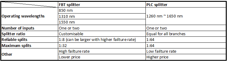
Also it is pretty clear visually shown on a infographic above (at least we hope so, as a lot of work are done to create above infograph), here’s a description of what you can see above.
Optical networks require signal being splitted somewhere in design to serve for multiple customers. Splitter technology has made a huge step forward in the past few years by introducing PLC (Planar Lightwave Circuit) splitter. It has proven itself as a higher reliable type of device compared to the traditional FBT (Fused Biconical Taper) splitter. While being similar in size and outer appearance, both types of splitters provide data and video access for business and private customers. However, internally the technologies behind these types vary, thus giving service providers a possibility to choose a more appropriate solution.
FBT splitter is made out of materials that are easily available, for example steel, fiber, hot dorm and others. All of these materials are low-price, which determines the low cost of the device itself. The technology of the device manufacturing is relatively simple, which has the impact on its price as well. In scenario where multiple splits are needed, the size of the device may become an issue. It is important to keep in mind that splitters are being deployed in the fields either in cabinets or in strand mountings, so the size of device plays a critical role. FBT splitters only support three wavelengths (850/1310/1550 nm) which makes these devices unable to operate on other wavelengths. Inability of adjusting wavelengths makes FBT splitters less customizable for different purposes. Moreover, the devices are to a high extent temperature sensitive, providing a stable working range of -5 to 75 C. In certain areas, such as Scandinavian countries this temperature restrictions may be crucial. The signal processed by FBT splitters cannot be splitted evenly due to lack of management of the signals
PLC splitter manufacturing technology is more complex. It uses semiconductor technology (lithography, etching, developer technology) production, hence it is more difficult to manufacture. Therefore, the price of the device is higher. However, there is a number of advantages the device possesses. The size of the device is compact, compared to FBT splitters, making it suitable for density applications. PLC splitter operates at wider temperature range (-40 to 85 C), allowing its deploying in the areas of extreme climate. The split ratio goes up to 64, providing a high reliability. Furthermore, the signal can be split equally due to technology implemented. A range of wavelengths (1260 – 1650 nm) is provided, so the wavelengths are adjustable. Critical points of the device that might fail are input and output, so the general risk of failure is low.
5G is the “fifth generation” of wireless networks. It will cover a wide range of devices, including both mobile and fixed network infrastructure, i.e. both mobile smartphones, wearables and settled machines will be wireless. So does that mean in future we will need no fiber cables running around?
At first glance, people may think 5G wireless will work via radio signals and no fiber will be used. On the contrary, the success of future 5G significantly depends on fiber.
Beneath the surface of the world’s wireless infrastructure lies a big net interwoven by the fiber optic cables. And at present 90% of all internet traffic travels over wireline fiber, even if it finally terminates in a wireless device.

5G is targeted at a connection speed of 1-10 Gbps, which is ten to hundred times higher than 4G. The overwhelming traffic to data centers will demand a transport media that is capable of high bandwidth and long distance, and fiber is the best future-proof choice among all mediums. For some big companies who know the role of fiber have invested more on it in preparing for 5G deployment, such as Verizon.

In order to meet the 5G promised performance goals (see the chart below), there needs to be more fiber deployed worldwide. Because the final target is not only about higher speed, but the sub-millisecond latency, network diversity, availability and coverage that all require a solid foundation of fiber.
| 1. 1-10Gbps connections to end points in the field (i.e. not theoretical maximum) |
| 2. 1 millisecond end-to-end round trip delay (latency) |
| 3. 1000x bandwidth per unit area |
| 4. 10-100x number of connected devices |
| 5. (Perception of) 99.999% availability |
| 6. (Perception of) 100% coverage |
| 7. 90% reduction in network energy usage |
| 8. Up to 10 year battery life for low power, machine-type devices |
The goals of 5G network diversity, availability and coverage can be obtained by wider deployment of small cell sites/distributed antenna systems (DAS) interconnected by fiber. Small cell sites/DAS (100-200 m/less than 30 m) are closer to users in location (on light or utility poles) compared with macro cell site (3-6 km), and can support a variety of technologies and frequencies.

By deploying more small cell sites/DAS, there can be fewer terminal users covered by each site and thus enabling higher per-user capacities. If the small cell sites/DAS need to work well in future 5G, the backhaul must be fiber since copper or air cannot support the immense amount of traffic that will be generated by 5G centralized radio access network (C-RAN).

In addition to ability, also considering the cost-effectiveness and TCO (total cost of ownership), fiber to the cell sites or tower is deemed the superior option. And of course more connections from these sites to data centers mean more fiber will be installed.
5G wireless will not abandon fiber. Instead its deployment will greatly rely on the availability of fiber infrastructure. Also the fiber will largely boost the capacity and lower latency in future generations of wireless networks.
Booster amplifier—placed immediately after the transmitter, it is used to increase the output power at the beginning of the link.
In-line amplifier—placed in the middle of an optical link, it is used to increase the power level at the end of the transmission line according to receiver sensitivity.
Pre-amplifier—placed in front of an optical receiver, it is used to compensate the attenuation of the link.
Dual fiber Mux/Demux uses the same wavelength for dual-way transmission. It means the TX port and RX port of every duplex channel port supporting the same wavelength. The WDM Mux/Demux with dual fiber line ports installed on the two ends of the network could be the same.
For single fiber Mux/Demux, all the wavelengths flow in one direction. And the TX port and RX port of every duplex channel port support two different wavelengths. If you choose a single fiber Mux/Demux on one side of the network, on the other side, there should be a single fiber Mux/Demux which supports the same wavelengths but has the reverse order on the TX port and RX port of every duplex channel port.
The special ports of DWDM Mux/Demux include express and upgrade port, monitor port and 1310nm port.
Express and Upgrade Port—For DWDM Mux/Demux, the purpose of an upgrade port is to add, drop, or pass through C-band DWDM channels not already in use, i.e., only channels that reside in the band 1530-1565 nm. If the DWDM Mux/Demux also has an express (or expansion) port, then that port is normally used for additional channels residing outside the C-band, such as most of the CWDM channels.
Monitor Port—This port is used to monitor or test the power signal coming out of a muxed DWDM or before it gets demuxed from the signal coming through the fiber network, usually at a 5% or less power level.
1310nm Port—The 1310nm port is used in some legacy networks and sometimes as a return path. With the special designed 1310nm port, the signal running through ordinary fiber optic transceivers can be combined together with other wavelengths.
The IL of a WDM product is given as the maximum insertion loss occurring at the channel port with the highest loss. Usually, IL is a focus point during the selection of DWDM Mux/Demux. The following table shows the typical and maximum insertion loss of FS DWDM Mux/Demux.
| AAWG technology | 3 dB (Typical) | 4.5 dB (Max) |
| TAWG technology | 3.5 dB (Typical) | 5 dB (Max) |
The picture below demonstrates the max insertion loss values of 40 channels DWDM Mux/Demux offered by different vendors for your reference.

FTTX is a generalization for several configurations of fibre deployment, arranged into two groups: FTTP/FTTH/FTTB (Fiber laid all the way to the premises/home/building) and FTTC/N (fiber laid to the cabinet/node, with copper wires completing the connection).
Ribbon optical cable offers an optimum alternative for campus, building and data center deployments where higher fiber counts (more than 24 fibers) are required. The fiber counts of it are available with 2-, 4- and 8-ribbon, while 12-ribbon is the most popular in newly designed networks. 24-ribbon is becoming popular in the U.S., when it is terminated or spliced it is treated as 2 x 12 by splitting the 24.

The main job of optical fibers is to guide lightwaves with a minimum of attenuation (loss of signal). Multimode fiber and single-mode fiber are the general two categories of optical fiber in use today. Single-mode fiber has a much smaller core that allows only one mode of light at a time through the core. As a result, the fidelity of the signal is better retained over longer distances, and modal dispersion is greatly reduced. These factors attribute to a higher bandwidth capacity than multimode fibers are capable of. For its large information-carrying capacity and low intrinsic loss, single-mode fibers are preferred for longer distance and higher bandwidth applications, including DWDM.